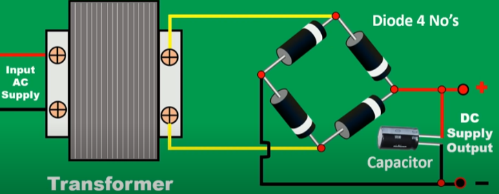
How to check the diode bridge Circuit Diagram AC to DC conversion is achieved using devices called rectifiers. These devices convert the alternating voltage of AC into a constant voltage of DC. Rectifiers can be diode-based (half-wave or full-wave) or semiconductor-based (such as bridge rectifiers).
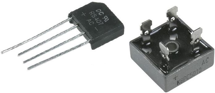
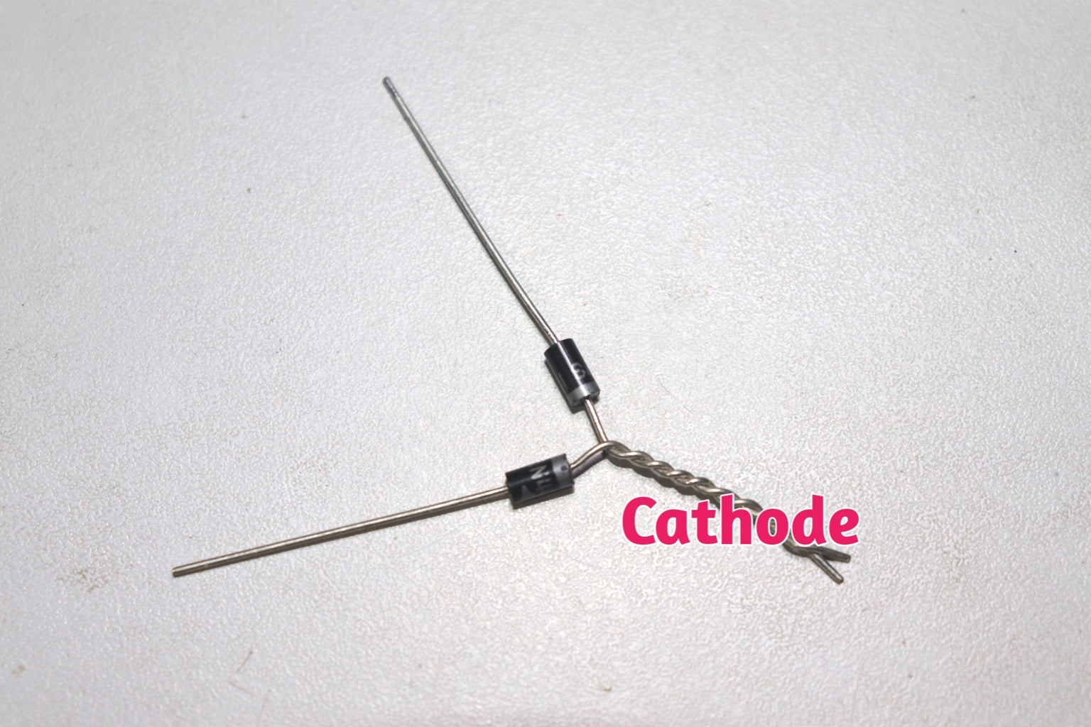
A diode bridge is a simple arrangement of diodes that can be used to convert an AC signal into a DC signal. Circuit. Explanation. A diode permits current to flow in a single direction only, from the anode to the cathode. Which is in the direction of the symbol shown below:
Bridge Rectifier Explained: Turning AC to DC! ⚡ Circuit Diagram
AC to DC using diode Bridge and Capacitor - full Bridge Rectifierjust use diode bridge and capacitor to transform the voltage from AC to DC, this is a simple
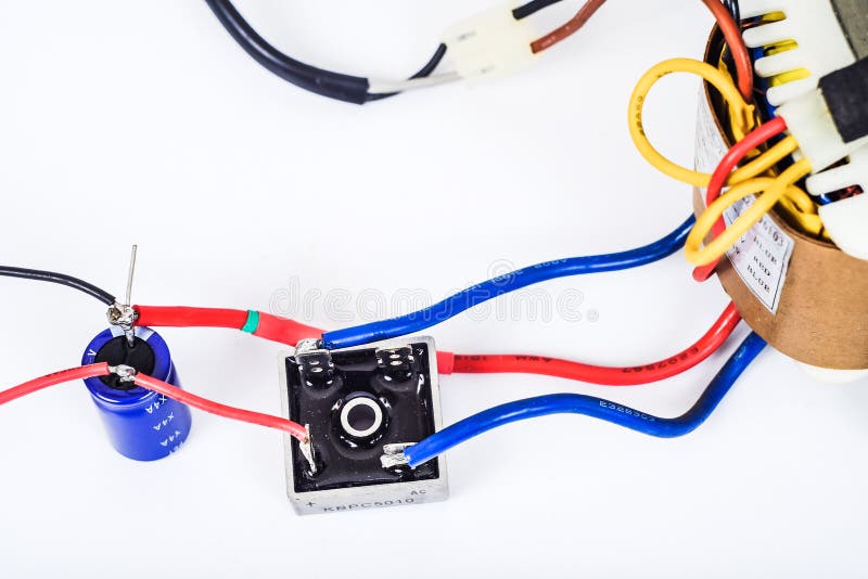
An AC power source is required for powering major appliances but almost all electronic circuits require a steady DC supply. A simple rectifier circuit described in [[wysiwyg_imageupload::]]this project converts the input from AC source to DC voltage. Firstly, the AC input from mains is stepped down to a lower value of voltage. This AC supply is then passed through a rectifier circuit to remove

How to Convert AC to DC using Diodes Circuit Diagram
The only way to do that is by using AC current, which switches between positive and negative voltages at 50-60Hz. In order for electronic circuits to work, we must convert this stepped-down AC voltage to a flat, stable DC voltage. That's where the bridge rectifier comes in, and in this case a full-wave rectifier. Learn How to Convert AC to DC using Diode, Transformer, Capacitor, Bridge Rectifier.Electronic Components Required:1. Diode = 4 Nos2. Step Down Transformer =