DIY PC Fan Controller 7 Steps Circuit Diagram This circuit uses a thermistor as a sensor, the thermistor resistance decrease when a temperature increase. When the temperature increases the thermistor resistance decrease until the voltage set point that adjusts by potentiometer higher than Vgs threshold, MOSFET change to ON state and make a 12 volts fan start and rotating speed faster when a temperature hotter.
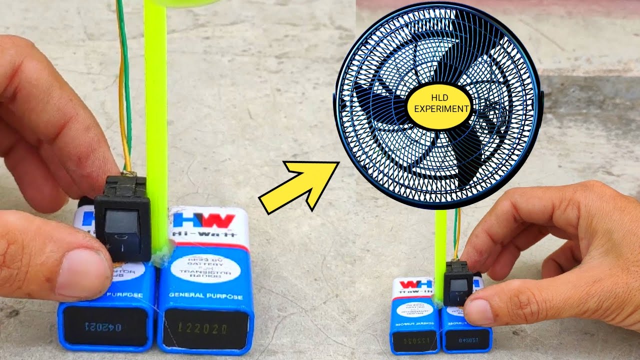
In this video, we are going to show you making a simple DC fan speed controller circuit at home easily. It is a very cheap & useful electronics circuit.To ma
How to Make a Simple Temperature Control Fan Speed Circuit Diagram
In this video, I'm going to show you making a speed control circuit. Using this circuit you can control any 12v circuit easily. To make this circuit you migh

Voltage Regulator Circuit Connection. Recognize the terminals of all the components for positive and negative terminal connections. Choose the ceiling fan or any AC motor provided it should be rated below 200 watts (According to the values of the components selected); Take a zero board or printed circuit board (PCB) and connect the circuit as given in the below diagram. Depending on the required current delivery, control circuits for large and small fans could be designed from discrete components or from an integrated fan controller. Building these circuits or systems involve selection of a few simple elements: If you want to build a fan control fan control circuit, you must know what type it will connect

Simple Fan regulator circuit using TRIAC and DIAC Circuit Diagram
my problem is to simulate the replaced Fan for control system. control system checks the feedback from Fan . i tried to simulate it with a 555 ic but feedback must be dynamic and propper to pwm from controller. do you have any suggestion. thanks in advance.

We'll show you how to make a heating sensor circuit for very little money in this video/How to make temperature sensor circuit fan control at home / how temp
