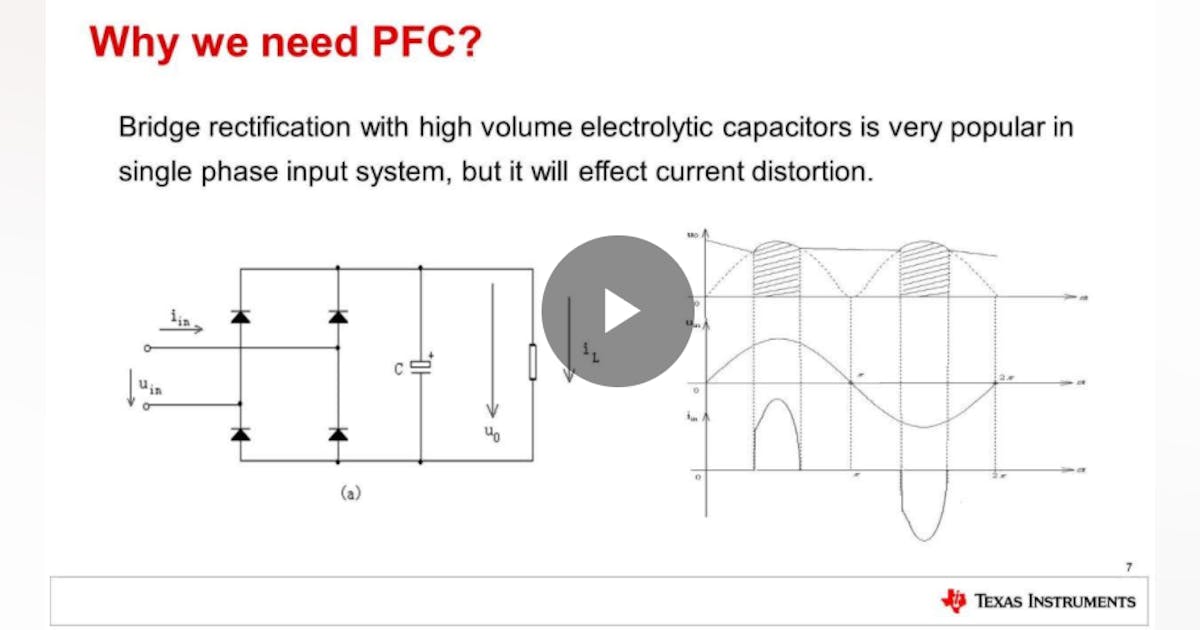
Design the following Power factor correction Circuit Diagram What are a power factor and power factor correction? Many electronic circuits have a capacitor at the input of the power supply so as to operate with DC voltage. This capacitor might causes a phase shift between the sinusoidal AC power supply voltage and current and the power factor (PF) will drop. A power factor correction (PFC) circuit
Power factor correction (PFC) basics. 00:09:09. Power factor correction (PFC) classification and control laws. 00:07:42. Power factor correction (PFC) topology comparison. 00:11:59. How to design an efficient power factor correction (PFC) circuit. 00:08:14. Power factor correction (PFC) design example. 00:07:22 In this video we will start by explaining how to build a power correction factor circuit for an inductive load distribution system. We will go into the backg

PDF Design and Control for Power Factor Correction Circuit Diagram
A SIMPLE explanation of Power Factor Correction (PFC). Learn what power factor correction is, why it is needed, and the formula & equation for power factor correction. Generally, it is used in power supply design for more than 100W. This type of power factor correction circuit consists of high-frequency switching elements like a diode, SCR

Power Factor Versus DistortionPower Factor Versus Distortion Table 1 several sources: the feedforward signals, the feed-back loops, the output capacitor, the inductor and the input rectifiers. An active power factor corrector can easily achieve a high input power factor, usually much greater than 0.9. But power factor is not a sensitive meas-

Designing a Power Factor Correction Circuit Circuit Diagram
power factor would represent the ratio between beer and foam. A high power factor would mean little to no foam in the glass and the generated power is well utilized. For a low power factor, a significant portion of the glass is filled with foam due to the poor power utilization. To obtain the same amount of beer as the high power factor